 PCB & PCBA Manufacturer
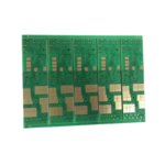
Automotive FR4 PCB – AEC-Q100 Ready Design
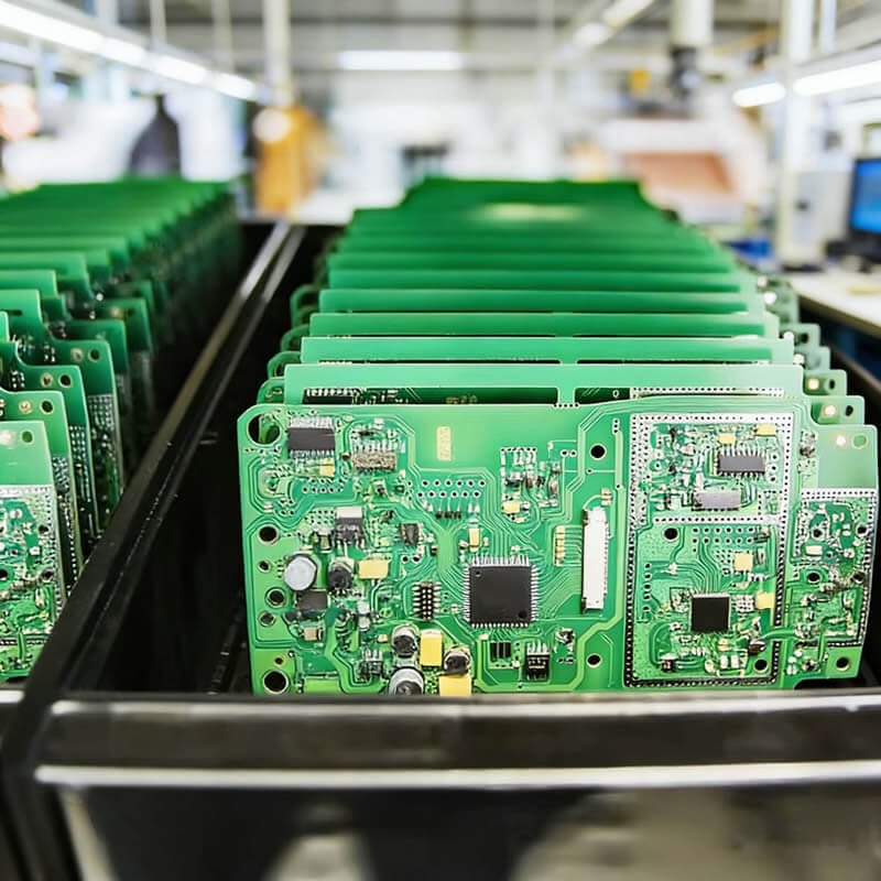
The automotive industry has undergone a dramatic transformation. Modern vehicles contain over 100 PCBs – from engine control units (ECUs) and advanced driver-assistance systems (ADAS) to infotainment and battery management systems (BMS). These applications demand extreme reliability, wide temperature operation, and zero-defect quality.
The Automotive FR4 PCB is engineered to meet these challenges, designed to be AEC-Q100 ready and manufactured under IATF 16949 certified processes.
What Does AEC-Q100 Mean for PCBs?
AEC-Q100 is the automotive industry’s stress test qualification standard for integrated circuits. While it applies primarily to ICs, an AEC-Q100 ready PCB means:
| Requirement | What We Deliver |
|---|---|
| Temperature Grade 1 | -40°C to +125°C operation (under-hood applications) |
| Temperature Grade 2 | -40°C to +105°C (passenger compartment) |
| Thermal cycling resilience | No via cracking or delamination after 1000+ cycles |
| High temperature storage | 150°C for 1000 hours – no degradation |
| Humidity resistance | 85°C / 85% RH for 1000 hours – no corrosion |
| Vibration tolerance | Robust pad and via design for mechanical stress |
Automotive Temperature Grades
| Grade | Temperature Range | Typical Applications |
|---|---|---|
| Grade 0 | -40°C to +150°C | Engine compartment, exhaust systems |
| Grade 1 | -40°C to +125°C | Most under-hood ECUs, transmission control |
| Grade 2 | -40°C to +105°C | Passenger compartment modules |
| Grade 3 | -40°C to +85°C | Infotainment, comfort electronics |
Our Automotive FR4 PCB supports Grade 1 and Grade 2 as standard. Grade 0 is available with specialized materials – contact us for requirements.
Key Design Features for Automotive PCBs
| Feature | Purpose | How We Deliver |
|---|---|---|
| High TG material | Withstand under-hood temperatures | TG 170°C FR4 standard |
| Thick copper for power | High current for motors, pumps, heaters | 2-4 oz copper on power layers |
| Controlled impedance | ADAS cameras, radar, high-speed interfaces | ±10% standard, tighter on request |
| Extended creepage | High voltage isolation (EV/HEV) | Per IEC 60664 automotive standard |
| Thermal vias | Heat dissipation from power components | Dense via arrays under MOSFETs |
| Robust annular rings | Prevent via cracking under vibration | No reduction – full annular ring |
| Tented & filled vias | Prevent solder wicking and contamination | Via-in-pad with filling available |
Technical Specifications for Automotive FR4 PCB
| Parameter | Automotive Grade Capability |
|---|---|
| Layer count | 2 to 12 layers (higher on request) |
| Base material | High TG FR4 (TG 170°C) – standard |
| Quality standard | IATF 16949 certified processes |
| Temperature range | -40°C to +125°C (Grade 1) |
| Board thickness | 0.8mm – 2.4mm |
| Copper weight | 1 oz – 4 oz (2-4 oz recommended for power) |
| Min trace width/spacing | 4 mil / 4 mil (3 mil available) |
| Min drill size | 0.20mm mechanical |
| Controlled impedance | ±10% standard, ±8% on request |
| Surface finish | ENIG (preferred), Immersion Silver, HASL Lead-Free |
| Solder mask | Automotive-grade – high durability, high contrast |
| Inspection | 100% AOI + X-Ray for BGA |
| Documentation | PPAP Level 3 available |
Applications for Automotive FR4 PCB
| Application | Temperature Grade | Special Requirements |
|---|---|---|
| Engine Control Unit (ECU) | Grade 1 | High temp, vibration resistance |
| Transmission Control | Grade 1 | Thermal cycling, reliability |
| ADAS (cameras, radar, LiDAR) | Grade 2 | Controlled impedance, signal integrity |
| Infotainment system | Grade 3 or 2 | High density, fine pitch components |
| Battery Management System (BMS) | Grade 1 or 2 | High voltage isolation, heavy copper |
| Electric power steering | Grade 1 | High reliability, zero defect |
| Body control module | Grade 2 | Mixed signal, cost-effective |
| LED headlight driver | Grade 1 or 0 | Thermal management, high current |
| DC-DC converter (EV) | Grade 1 | Heavy copper, high temp |
Standard vs. Automotive Grade – Quick Comparison
| Feature | Standard FR4 PCB | Automotive FR4 PCB |
|---|---|---|
| Temperature range | 0°C to +70°C or -20°C to +85°C | -40°C to +125°C (Grade 1) |
| Material TG | TG 130°C – 140°C | TG 170°C minimum |
| Quality system | ISO9001 | IATF 16949 certified |
| Inspection | AQL sampling | 100% AOI + X-Ray |
| Defect target | < 1000 ppm | < 10 ppm (zero defect culture) |
| Traceability | Lot-level | Lot-level with date code on each board |
| Documentation | COC (test report) | PPAP Level 3 available |
| Thermal cycling | Not required | 1000+ cycles -40°C to +125°C |
| Cost | Baseline | +30-60% depending on requirements |
Zero Defect Manufacturing for Automotive
Automotive customers demand near-zero defects (typically < 10 ppm). Our automotive manufacturing process includes:
| Process Control | What It Means |
|---|---|
| Statistical Process Control (SPC) | Real-time monitoring of critical parameters |
| 100% AOI | Every board inspected – no sampling |
| X-Ray inspection | For BGA, QFN, and other hidden solder joints |
| Flying probe / fixture test | 100% electrical test |
| Microsection analysis | Periodic cross-section validation |
| Controlled storage | Temperature and humidity controlled |
| Lot segregation | No mixing of different production lots |
Why Manufacture Your Automotive FR4 PCB With Us?
| Feature | What You Get for Automotive Applications |
|---|---|
| IATF 16949 certified | Automotive quality management system |
| AEC-Q100 ready design | Built for automotive temperature and reliability |
| PPAP Level 3 | Full documentation package available |
| 100% AOI + X-Ray | Every board inspected |
| Thermal cycling tested | Validated for -40°C to +125°C |
| Heavy copper capability | 2-4 oz for power distribution |
| Full traceability | Lot-level with date codes on each board |
Order Process for Automotive PCB
Upload your Gerber files – specify automotive application
Receive DFM report with automotive-specific recommendations
PPAP documentation – provided upon request
Fabrication – IATF 16949 controlled processes
100% inspection – AOI, X-Ray, electrical test
Traceability marking – date code / lot number on each board
Secure shipping with full documentation package