 PCB & PCBA Manufacturer


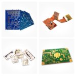
1.6mm FR4 PCB Board – Most Common Thickness
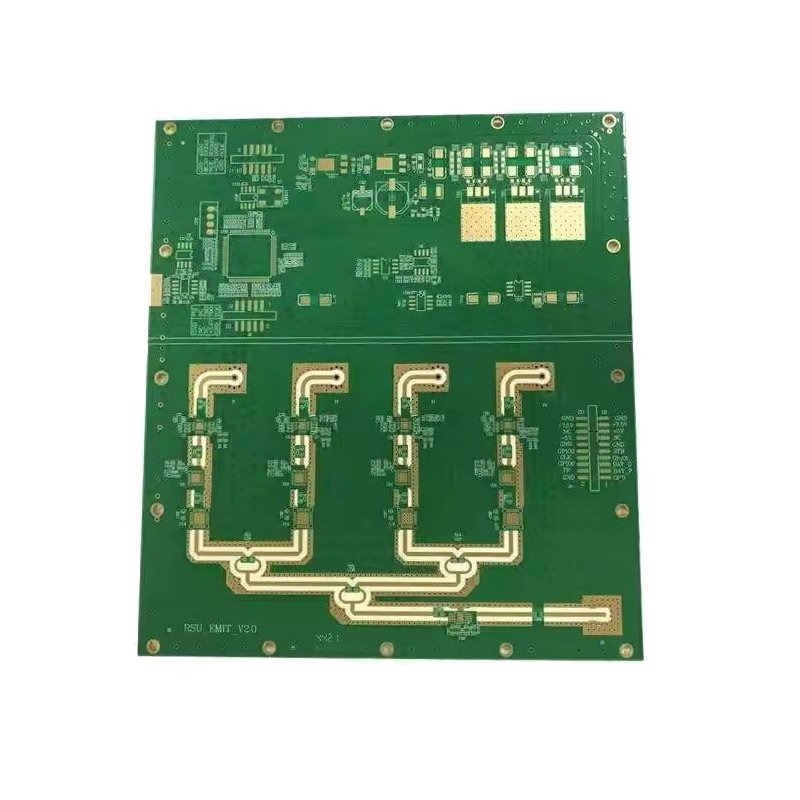
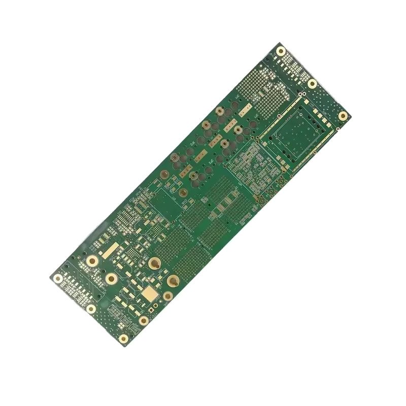
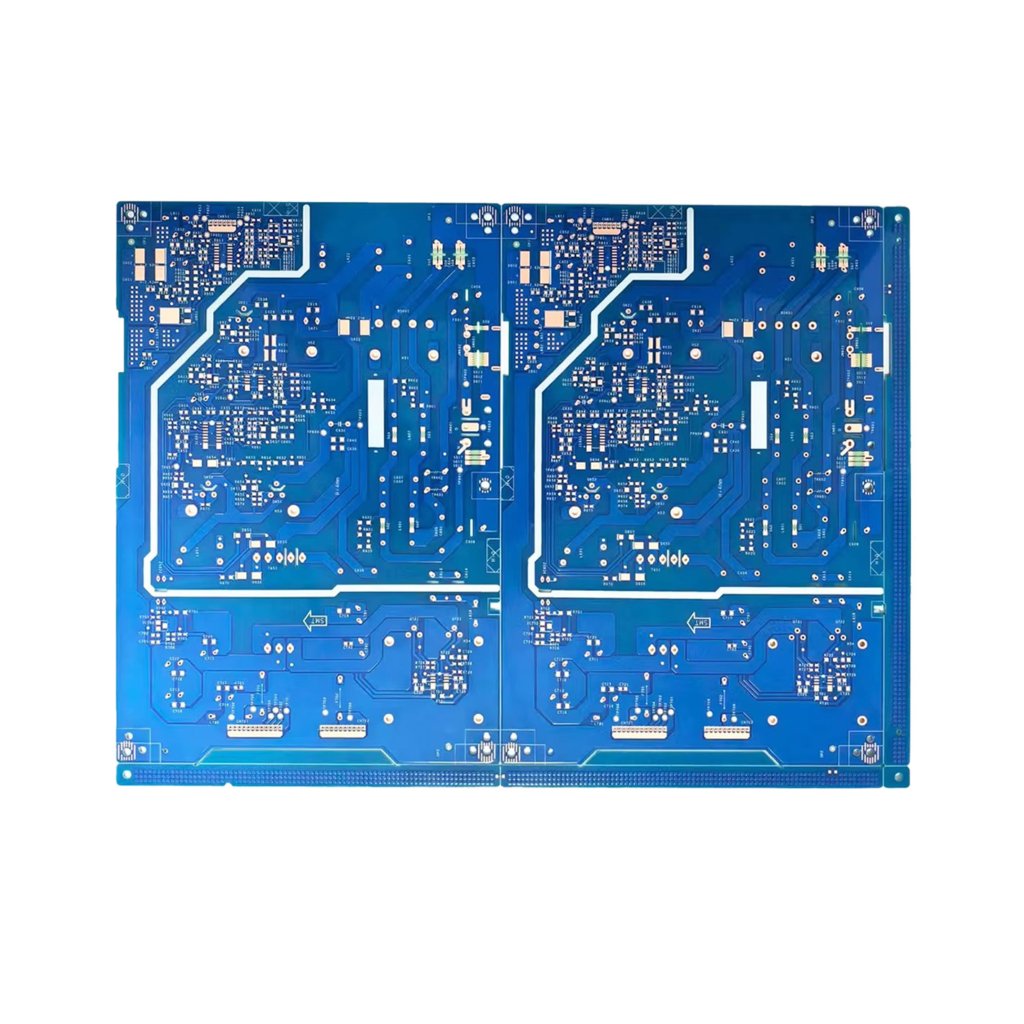
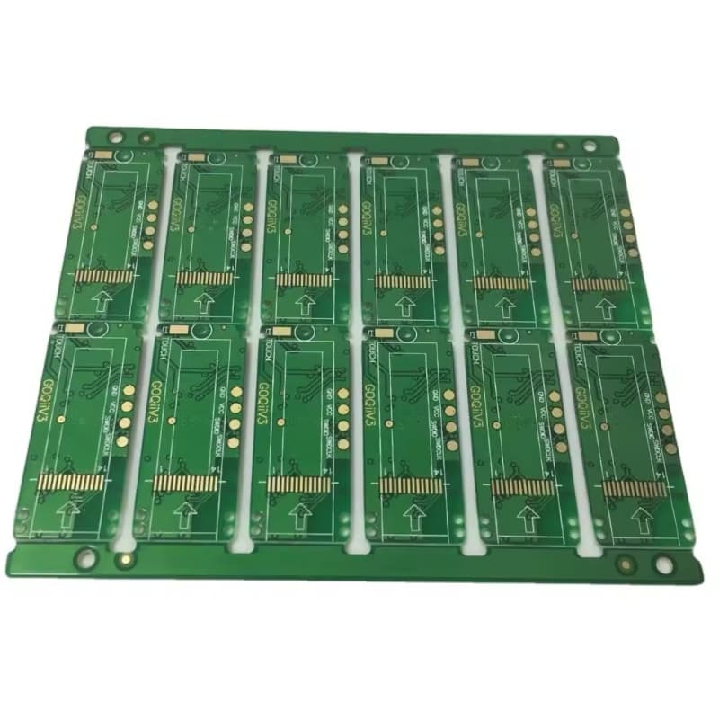
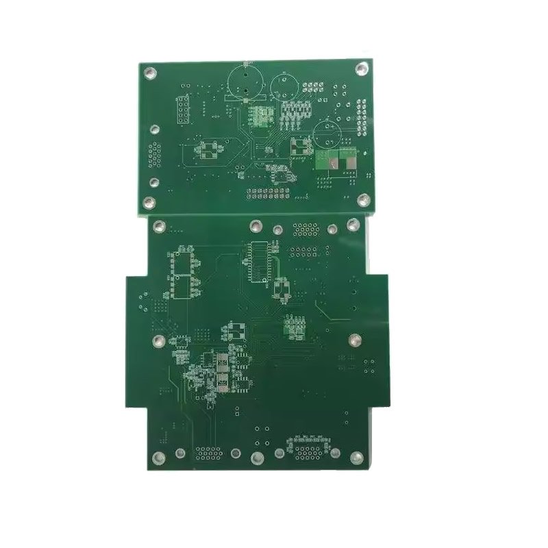
The 1.6mm FR4 PCB Board (0.063 inches, also known as 1/16 inch) is the global industry standard thickness for printed circuit boards.
For engineers and PCB designers, 1.6mm is the default choice unless there is a specific reason to use a thinner or thicker board. Because it is the most widely used thickness globally, it offers significant advantages in cost, availability, and manufacturing speed.
Why 1.6mm is the Industry Standard
| Reason | Explanation |
|---|---|
| Historical precedent | Derived from 1/16″ (0.0625″) standard in early electronics |
| Mechanical strength | Rigid enough for most connector types and handling |
| Component support | Sufficient thickness for standard through-hole components |
| Connector compatibility | PCIe, Eurocard, and many edge connectors designed for 1.6mm |
| Manufacturing ubiquity | Every PCB fabricator stocks this material |
| Lowest cost | High volume = lowest material cost |
Why Choose 1.6mm?
| Advantage | Benefit |
|---|---|
| Lowest cost | Most economical thickness – material always in stock, no special setup |
| Fastest turnaround | Prototype lead times are shortest for 1.6mm |
| Highest availability | No material procurement delays |
| Proven mechanical strength | Rigid – withstands vibration, shock, handling |
| Industry standard connectors | Fits PCIe, Eurocard, standard card guides without modification |
| Compatible with all layer counts | Works from 2 layers to 12+ layers |
| Compatible with all finishes | ENIG, HASL, OSP, Immersion Silver |
How Thickness Affects Mechanical Properties
| Thickness | Rigidity | Flexibility | Typical Applications |
|---|---|---|---|
| 0.6mm | Moderate | Some flex | Wearables, thin devices, tight spaces |
| 0.8mm | Good | Minor flex | Smartphones, tablets, thin consumer |
| 1.0mm | Good | Very little | Laptops, compact industrial |
| 1.2mm | Very Good | None | Standard consumer, industrial |
| 1.6mm | Excellent | None | Most applications (default) |
| 2.0mm | Very rigid | None | Heavy components, high vibration |
| 2.4mm+ | Extremely rigid | None | High power, heavy connectors |
Connector Compatibility
Many industry standard connectors and card formats are specifically designed for 1.6mm boards:
| Connector / Format | Designed Thickness |
|---|---|
| PCI Express (PCIe) | 1.6mm ±10% (1.44-1.76mm) |
| Eurocard (DIN 41612) | 1.6mm |
| VME / VXI bus | 1.6mm |
| CompactPCI | 1.6mm |
| PC/104 | 1.6mm |
| USB / HDMI connectors (through-hole) | 1.6mm recommended |
| SMT connectors (general) | 1.6mm – rigid for pick-and-place |
Note: If you are using edge connectors or card guides, 1.6mm is the safest choice unless your specific connector requires a different thickness.
Thickness Comparison – 1.6mm vs. Others
| Thickness | mm | inches | Best For |
|---|---|---|---|
| 0.6mm | 0.6 | 0.024″ | Wearables, thin devices, flex-rigid |
| 0.8mm | 0.8 | 0.031″ | Smartphones, tablets |
| 1.0mm | 1.0 | 0.039″ | Laptops, compact industrial |
| 1.2mm | 1.2 | 0.047″ | Consumer electronics |
| 1.6mm | 1.6 | 0.063″ | Most applications – DEFAULT |
| 2.0mm | 2.0 | 0.079″ | Heavy components, high vibration |
| 2.4mm | 2.4 | 0.094″ | High power, heavy copper |
When NOT to Use 1.6mm
| Scenario | Better Thickness | Why |
|---|---|---|
| Wearable device | 0.6-0.8mm | Too thick, heavy for wrist |
| Extremely thin smartphone | 0.8-1.0mm | 1.6mm too thick for thin chassis |
| HDI / BGA dense design | 1.0-1.2mm | Thinner = easier laser drilling |
| Very high frequency (RF) | Determined by stackup | Electrical performance priority |
| High current / heavy copper | 2.0-2.4mm | Supports thick copper, heavier traces |
| Heavy component support | 2.0-2.4mm | Large transformers, connectors need more rigidity |
| High vibration environment | 2.0mm+ | Thicker = stiffer = less flex damage |
Technical Specifications for 1.6mm FR4 PCB Board
| Parameter | Capability |
|---|---|
| Board thickness | 1.6mm (0.063″, 1/16″) – industry standard |
| Tolerance | ±10% (IPC Class 2) – typically ±0.13-0.16mm |
| Layer count | 2 to 12+ layers |
| Base material | FR4 (Standard TG or High TG 170°C) |
| Copper weight | 1 oz standard (2-6 oz available) |
| Min trace width/spacing | 4 mil / 4 mil (3 mil available) |
| Min drill size | 0.20mm |
| Surface finish | ENIG, HASL Lead-Free, OSP, Immersion Silver |
| Solder mask color | Green (standard), Blue, Red, Black, White, Yellow |
| Silkscreen color | White (standard), Black, Yellow |
| Aspect ratio | 10:1 (board thickness : smallest drill diameter) |
| Inspection | 100% AOI + electrical test |
1.6mm Aspect Ratio for Vias
Aspect ratio = Board thickness / Drill diameter.
With 1.6mm board thickness:
0.20mm drill: Aspect ratio 8:1 (within standard capability)
0.25mm drill: Aspect ratio 6.4:1 (very comfortable)
0.30mm drill: Aspect ratio 5.3:1 (extremely reliable)
Recommendation: For high reliability, use 0.25mm or larger drill with 1.6mm thickness.
Applications for 1.6mm FR4 PCB Board
| Application | Why 1.6mm is Suitable |
|---|---|
| Industrial controls (PLCs, HMIs) | Rigid for DIN rail mounting, card guides |
| Consumer electronics | Cost-effective, proven reliability |
| Automotive modules (non-safety) | Good vibration resistance |
| Power supplies | Handles component weight + heat |
| Test & measurement equipment | Rigid for bench equipment |
| Telecom equipment | Fits standard card cages, connectors |
| Medical devices (non-implantable) | Reliable, standard connector fit |
| IoT gateways / hubs | Rigid enough for connectors |
| Development / evaluation boards | Industry standard – fits enclosures |
| Arduino / Raspberry Pi shields | 1.6mm is the shield standard |
Standard vs. 1.6mm – No Difference vs. Other Thicknesses
| Property | 1.6mm | Any Thickness | Difference? |
|---|---|---|---|
| Electrical performance | Same | Same (impedance depends on stackup, not total thickness) | No |
| FR4 material | Same | Same | No |
| Surface finish options | Same | Same | No |
| Solder mask | Same | Same | No |
| Copper weight support | Same | Same | No |
| Manufacturing quality | Same | Same | No |
| Price | Lowest | Higher (thinner/thicker more costly) | Yes – 1.6mm cheapest |
| Lead time | Fastest | Slower (special material orders) | Yes – 1.6mm fastest |
The only differences: 1.6mm is cheaper, faster, and more available – same electrical performance.
Why Manufacture Your 1.6mm FR4 PCB Board With Us?
| Feature | What You Get |
|---|---|
| Industry standard thickness | 1.6mm – most common board thickness |
| Lowest cost | Most economical thickness due to volume |
| Fastest turnaround | Material always in stock, no delays |
| 2 to 12+ layers | Any complexity |
| All surface finishes | ENIG, HASL Lead-Free, OSP, Immersion Silver |
| High TG available | 170°C for lead-free assembly (on request) |
| Heavy copper available | Up to 6 oz (on request) |
| Controlled impedance | Available (on request) |
Order Process for 1.6mm FR4 PCB Board
Upload your Gerber files
1.6mm thickness confirmed – default unless specified
Fabrication – fastest lead times (material in stock)
100% electrical test
Secure shipping
Tip: If you don’t specify thickness, 1.6mm will be used by default at most PCB manufacturers worldwide.