Rigid Flex Rigid PCB – Multiple Rigid Sections
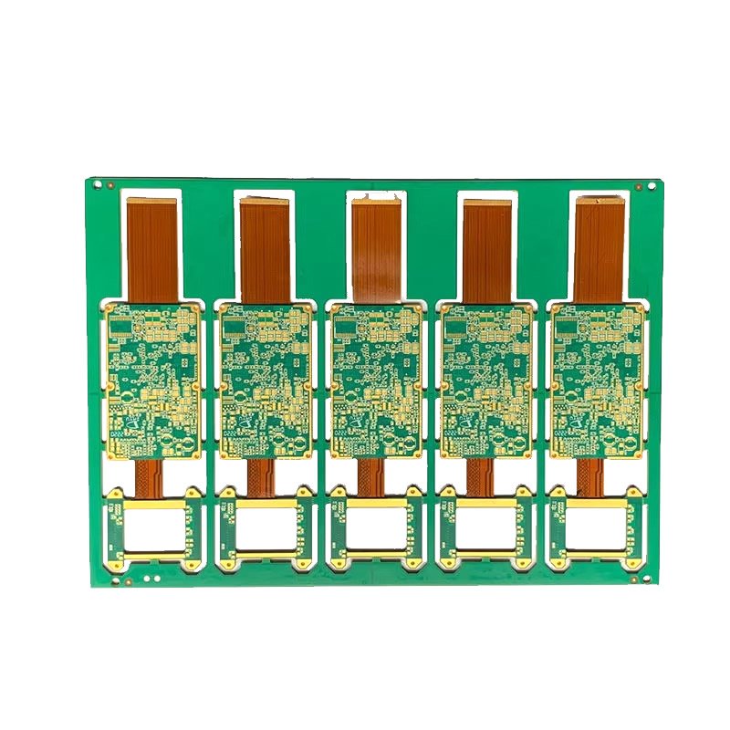
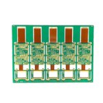
A Rigid Flex Rigid PCB (also known as a multi-section rigid flex) features two or more rigid FR4 sections connected by flexible polyimide sections – all in one integrated board.
Instead of using separate rigid PCBs connected by cables, connectors, or wire harnesses, you get a single board with multiple rigid areas that can be positioned at different angles, folded together like a book, or placed in separate compartments of an enclosure.
If your product has multiple electronic modules that need to communicate but are physically separated, rigid flex rigid is the ideal solution.
What is a Rigid Flex Rigid PCB?
| Feature | Description |
|---|---|
| Multiple rigid sections | 2, 3, 4, or more separate FR4 areas on one board |
| Flex sections between them | Thin polyimide connectors – bend and fold |
| Continuous traces | Copper traces run from rigid section to rigid section through flex |
| No connectors | Eliminates board-to-board connectors and cables |
| Single integrated board | One PCB, one SKU, one assembly |
Think of it as: Multiple rigid PCBs that are “born connected” by flexible hinges.
Common Rigid Flex Rigid Configurations
| Configuration | Rigid Sections | Flex Sections | Typical Use |
|---|---|---|---|
| 2-section (simple) | 2 | 1 | Laptop hinge, two-board system |
| 3-section (Z-fold) | 3 | 2 | Foldable phone, stackable modules |
| 4-section (parallel) | 4 | 3 | Multi-panel display |
| Complex (multiple tails) | 3+ | 2+ | Industrial equipment, medical scopes |
Examples:
2-Section Configuration:
[ Rigid A ] ==== flex ==== [ Rigid B ]

3-Section Z-Fold Configuration:
[ Rigid A ] ==== flex ==== [ Rigid B ] ==== flex ==== [ Rigid C ]
     ↓                           ↓                           ↓
  (folds on top of B)         (middle)         (folds under B)

Parallel Configuration:
[ Rigid A ] === flex === [ Rigid B ] === flex === [ Rigid C ] === flex === [ Rigid D ]
Rigid Flex Rigid vs. Multiple Separate PCBs
| Approach | Components | Connections | Assembly | SKUs |
|---|---|---|---|---|
| Multiple separate PCBs | PCB #1, PCB #2, cables, 2-4 connectors | Cables + connectors | Complex (multiple placements) | 3-5 |
| Rigid Flex Rigid | Single integrated board | 0 connectors | Simple (one placement) | 1 |
Example: Laptop motherboard + display connection
| Approach | What’s Needed |
|---|---|
| Traditional | Motherboard PCB + Display PCB + Hinge cable + 2 connectors |
| Rigid Flex Rigid | Single board – motherboard rigid section + flex through hinge + display rigid section |
Why Choose Rigid Flex Rigid Over Multiple PCBs?
| Benefit | How Rigid Flex Rigid Delivers |
|---|---|
| No board-to-board connectors | Eliminates connector cost and connector failure modes |
| No cables | No cable BOM, no cable assembly labor |
| Higher reliability | Fewer interconnects = fewer failure points |
| Lower assembly cost | One board to place, not multiple boards + cables |
| Simpler inventory | One SKU instead of 3-5 SKUs |
| Better signal integrity | Continuous traces – no impedance discontinuities at connectors |
| Space efficient | Rigid sections can be folded on top of each other |
| Design flexibility | Rigid sections can be different sizes, shapes, thicknesses |
Multi-Section Configurations in Detail
2-Section (Simple Hinge)
| Feature | Description |
|---|---|
| Rigid Section A | Main board – processor, power, connectors |
| Flex Section | Hinge area – bends 90°-180° |
| Rigid Section B | Secondary board – display, sensors, buttons |
| Typical use | Laptop, clam shell device, medical monitor |
3-Section (Z-Fold)
| Feature | Description |
|---|---|
| Rigid Section A | Top section – folds over middle |
| Flex Section 1 | First hinge |
| Rigid Section B | Middle section – main components |
| Flex Section 2 | Second hinge |
| Rigid Section C | Bottom section – folds under middle |
| Typical use | Foldable phone, multi-panel display, portable instrument |
Parallel (Multiple Tails from One Rigid)
| Feature | Description |
|---|---|
| Rigid Section A | Main board – central processor |
| Flex Section 1, 2, 3… | Multiple tails extending from main board |
| Rigid Sections B, C, D… | Satellite boards – sensors, displays, I/O |
| Typical use | Medical scope (multiple sensors), industrial array |
Technical Specifications for Multi-Section Rigid Flex
| Parameter | Our Capability |
|---|---|
| Number of rigid sections | 2 to 8+ sections (depending on complexity) |
| Rigid layers per section | 2 to 12 layers (can vary per section) |
| Flex layers | 1 to 4 layers (same across all flex sections) |
| Flex thickness | 0.1mm to 0.4mm |
| Rigid thickness (per section) | 0.6mm to 2.4mm (can vary by section) |
| Copper – rigid sections | 1 oz to 6 oz |
| Copper – flex sections | 0.5 oz or 1 oz RA (rolled annealed) |
| Bend radius (between sections) | Minimum 10x flex thickness (static) |
| Surface finish | ENIG (preferred for multi-section) |
| Special features | Different thickness per rigid section, EMI shielding, stiffeners |
Design Considerations for Multi-Section Rigid Flex
| Consideration | Recommendation | Why |
|---|---|---|
| Number of flex sections | Minimize – each flex adds cost | More flex sections = more lamination cycles |
| Flex length | As short as possible | Longer flex = more material cost, more handling |
| Bend radius | ≥10x flex thickness | Prevents copper cracking |
| Flex direction | Same plane preferred | 3D folding adds complexity |
| Rigid section thickness | Can vary per section | Different components, different requirements |
| Via placement | No vias in flex sections | Vias crack when bent |
| Component placement | Rigid sections only | Flex too thin for components (without stiffeners) |
| Stiffeners | Add under connectors on flex tails | Prevents flex damage |
Applications for Multiple Rigid Sections
| Industry | Application | Why Multiple Rigid Sections |
|---|---|---|
| Laptop / tablet | Motherboard + display board | Flex passes through hinge |
| Foldable phone | 3-section Z-fold | Rigid sections fold on top of each other |
| Medical endoscope | Main unit + sensor head + control buttons | Multiple rigid sections in different housing areas |
| Aerospace avionics | Multiple modules in different compartments | Single board replaces multiple PCBs |
| Industrial equipment | Control panel + main unit + I/O board | Rigid sections in different enclosure areas |
| Camera system | Lens control + image processing + interface | Separate rigid sections connected by flex |
| Robotics | Base controller + arm sensors + end effector | Multiple rigid sections on moving joints |
Example: 2-Section Laptop Design
| Component | Location | Board Type |
|---|---|---|
| CPU, RAM, SSD, battery connector | Rigid Section A (under keyboard) | 6-layer rigid |
| Flex section | Hinge area (bends 135°) | 1-layer flex |
| Display driver, LCD connector, camera | Rigid Section B (behind display) | 4-layer rigid |
Single board replaces: Motherboard + cable + display board + 2 connectors.
Example: 3-Section Foldable Phone Design
| Component | Location | Board Type |
|---|---|---|
| Main processor, battery, RF | Rigid Section B (middle) | 8-layer rigid |
| Flex Section 1 | Left hinge | 1-layer flex |
| Display driver, sensors | Rigid Section A (left) | 4-layer rigid |
| Flex Section 2 | Right hinge | 1-layer flex |
| Secondary display, buttons | Rigid Section C (right) | 4-layer rigid |
Single board replaces: 3 separate PCBs + 4 connectors + 2 cables.
Why Choose Our Multi-Section Rigid Flex PCB?
| Feature | What You Get |
|---|---|
| Multiple rigid sections | 2 to 8+ sections on a single board |
| Varying rigid thickness | Different thickness per section (if needed) |
| RA copper for flex | Withstands repeated folding (dynamic flex) |
| No connectors between sections | Eliminate board-to-board connector failures |
| Engineering support | Flex routing, bend radius analysis, stackup design |
| Prototype available | Validate your multi-section design |
| ISO9001 & UL certified | Quality guaranteed |
Order Process for Multi-Section Rigid Flex
Upload Gerber files – specify number of rigid sections, flex sections, bend areas
Free DFM review – we verify flex routing, bend radius, section spacing
Receive quotation – based on complexity (more sections = higher cost)
First article (strongly recommended) – 5-10 pieces for validation
Production – built to your specifications
100% electrical test – including continuity across all sections
Secure shipping
New to multi-section rigid flex? First article is strongly recommended – validate folding, fit, and electrical continuity before mass production.