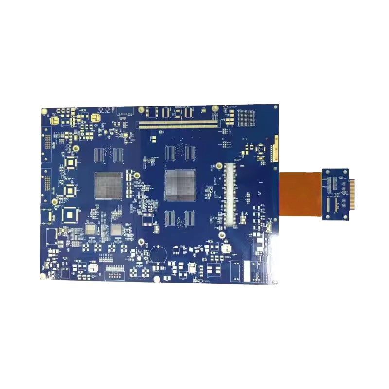
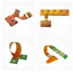
Flexrigid PCB – Rigid And Flexible PCB Combo
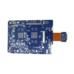
Flexrigid PCB (also known as rigid flex PCB) combines the best of both worlds: rigid FR4 sections for mounting heavy components, and flexible polyimide sections for bending and folding.
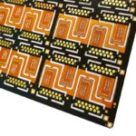
This single integrated board replaces traditional assemblies that use multiple rigid PCBs + connectors + cables – eliminating failure points, saving space, reducing weight, and simplifying assembly.
If your product needs to fold, fit into a curved enclosure, or withstand vibration, flexrigid is the answer.
What is a Flexrigid PCB?
| Feature | Description |
|---|---|
| Rigid sections | Standard FR4 material – holds ICs, connectors, batteries, large passives |
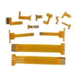
| Flexible sections | Thin polyimide (Kapton) – bends, folds, twists |
| Continuous traces | Copper traces run from rigid through flex to rigid – no connectors |
| Single board | One integrated PCB – not multiple boards connected by cables |
Think of it as: A rigid PCB that grows flexible “tails” where needed.
Flexrigid vs. Traditional Rigid + Cable + Rigid
| Approach | Components | Connections | Failure Points | Assembly |
|---|---|---|---|---|
| Traditional | Rigid PCB #1 + Cable + Rigid PCB #2 | 2 connectors + cable | 3+ (connectors, cable ends) | Complex |
| Flexrigid | Single integrated board | 0 connectors | 1 (the board itself) | Simple |
Fewer parts = fewer problems.
Why Choose Flexrigid Over Traditional Assembly?
| Benefit | How Flexrigid Delivers |
|---|---|
| No connectors | Eliminates connector cost and connector failure modes |
| No cables | No cable BOM, no cable assembly labor |
| Higher reliability | Fewer interconnects = fewer failure points |
| Space savings | Folds into 3D shapes – replaces multiple boards |
| Weight reduction | No connectors, no heavy cable harnesses |
| Better signal integrity | Continuous traces – no impedance discontinuities at connectors |
| Lower assembly cost | One board to place, not multiple boards + cables |
| Simpler inventory | One SKU instead of 3-5 SKUs |
Typical Flexrigid Construction
| Layer | Material | Thickness (typical) | Function |
|---|---|---|---|
| Coverlay (top) | Polyimide film | 0.5 mil | Protects flex copper |
| Flex copper | Rolled annealed (RA) copper | 0.5-1 oz | Signal traces in flex area |
| Polyimide core | Flexible base | 1-2 mil | Insulation between flex layers |
| Flex copper (bottom) | Rolled annealed (RA) copper | 0.5-1 oz | Signal traces in flex area |
| Coverlay (bottom) | Polyimide film | 0.5 mil | Protects flex copper |
| FR4 rigid sections (additional layers on rigid areas only) | FR4 + prepreg + copper | 0.4-1.6 mm | Component mounting, additional routing |
Key point: The flex core runs continuously. FR4 is added only where rigidity is needed.
Flexrigid Layer Combinations
| Type | Rigid Layers | Flex Layers | Total Construction | Typical Use |
|---|---|---|---|---|
| Simple | 2 (top/bottom) | 1 | 2 rigid + 1 flex | Wearables, simple sensors |
| Standard | 4 | 1-2 | 4 rigid + 1-2 flex | Medical devices, smartwatches |
| Complex | 6 | 2 | 6 rigid + 2 flex | Aerospace, industrial |
| Advanced | 8+ | 2-4 | 8+ rigid + 2-4 flex | High-density, military |
Most flexrigid designs use 4 rigid layers + 1-2 flex layers – this covers 80% of applications.
Flexrigid Design Considerations
| Consideration | Recommendation | Why |
|---|---|---|
| Bend radius | Minimum 10x flex thickness (static), 30x (dynamic) | Prevents copper cracking |
| Flex layer count | 1-2 layers typical | More layers = thicker = larger bend radius |
| Copper type | Rolled annealed (RA) for flex | ED copper cracks when bent |
| Via placement | Avoid vias in bend areas | Vias crack under flex stress |
| Component placement | Rigid sections only | Flex too thin for heavy parts |
| Coverlay | Use coverlay (not solder mask) on flex | Solder mask cracks |
| Stiffeners | Add under connectors on flex tails | Prevents flex damage during mating |
Applications Best Suited for Flexrigid
| Industry | Application | Why Flexrigid is Ideal |
|---|---|---|
| Wearables | Smartwatch, fitness band, AR/VR glasses | Fits curved wrist/head, holds battery/processor |
| Medical | Patient monitor, endoscope, hearing aid | High reliability, no connector failure, small size |
| Aerospace | Avionics, satellite electronics | Vibration resistant, weight reduction |
| Industrial | Robotics, CNC controllers | Dynamic flexing, rugged environment |
| Automotive | Camera modules, sensors | Vibration resistance, tight spaces |
| Consumer | Laptop, tablet, foldable phone | Hinge area – connects motherboard to display |
| Military | Portable radios, rugged devices | Reliability, shock/vibration resistance |
Flexrigid vs. Other PCB Types
| Feature | Rigid PCB | Flexible PCB (FPC) | Flexrigid (Combo) |
|---|---|---|---|
| Heavy component support | Excellent | Poor (needs stiffeners) | Excellent (on rigid sections) |
| Bendability | None | Excellent (entire board) | Excellent (flex sections only) |
| Space efficiency | Good | Excellent (folds anywhere) | Very good (folds where needed) |
| Connectors needed | Yes (board-to-board) | Fewer | None (rigid-to-rigid via flex) |
| Cost (low volume) | Low | Moderate | Higher |
| Cost (high volume) | Low | Low | Moderate (often lower total system cost) |
| Best for | Standard boxes | Simple bendable circuits | Complex folding with heavy components |
Common Flexrigid Applications – Detailed
| Device | Rigid Sections Hold | Flex Section Does |
|---|---|---|
| Smartwatch | Processor, battery, display driver | Wraps around wrist curve, connects to sensors |
| Hearing aid | Microphone, amplifier, battery | Folds to fit custom ear shape |
| Endoscope | Camera sensor, LED illumination | Bends through body cavity |
| Laptop | Motherboard components | Passes through hinge to display |
| Fitness band | Battery, vibration motor, optical sensor | Wraps around wrist |
| Automotive camera | Image sensor, processor | Connects through tight housing to main PCB |
Why Choose Our Flexrigid PCB?
| Feature | What You Get |
|---|---|
| True rigid-flex integration | Continuous traces from rigid through flex to rigid |
| RA copper standard for flex | Withstands repeated bending (dynamic flex) |
| No connectors needed | Eliminate connector failure points |
| Engineering support | Bend radius analysis, stackup design, material selection |
| Prototype available | Fast turnaround for design validation |
| Volume production | Scalable to your needs |
| ISO9001 & UL certified | Quality and safety guaranteed |
Order Process for Flexrigid PCB
Upload Gerber files – specify rigid and flex layers, bend areas
Free DFM review – we verify bend radius, via placement, stackup
Receive quotation – based on your design complexity
First article (recommended) – 5-20 pieces for validation
Production – built to your specifications
100% electrical test – including flex continuity
Secure shipping
New to flexrigid? We recommend first article (prototype) before mass production. Flexrigid is more complex than rigid PCB – validate your design first.