
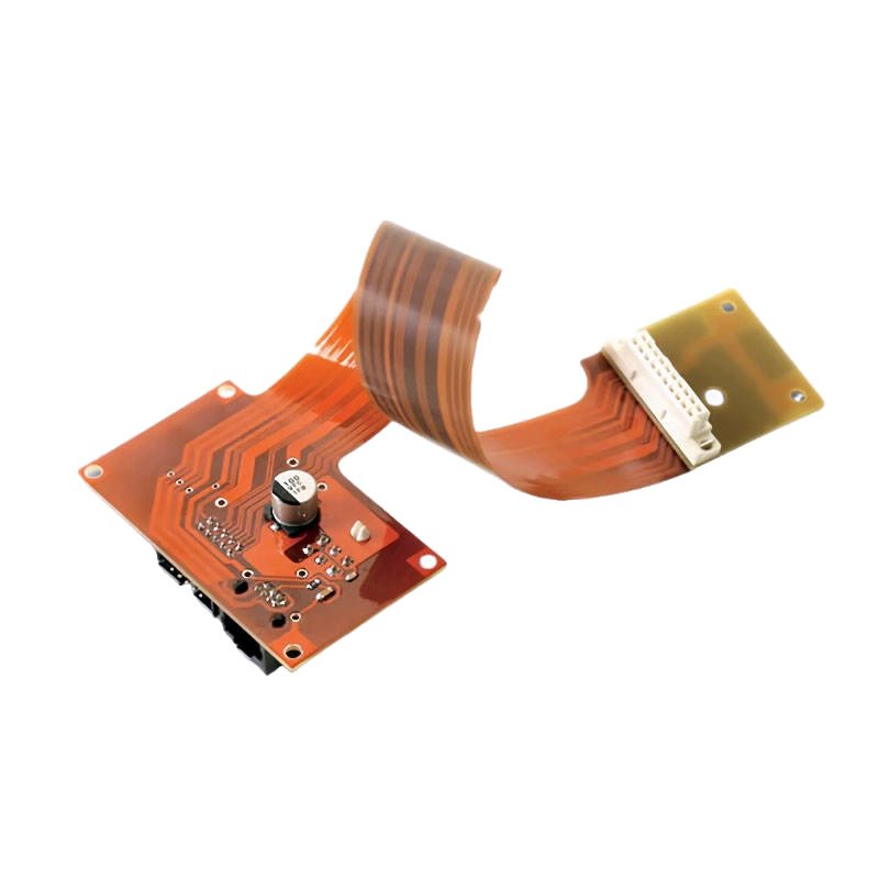
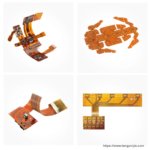

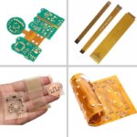
Bendable Circuit Board – Flex Printed Circuit Solution
A bendable circuit board (also known as a flexible printed circuit or FPC) is designed to bend, fold, and conform to shapes that rigid PCBs cannot achieve. Unlike rigid boards that crack or break when stressed, bendable circuit boards use thin polyimide material and rolled annealed (RA) copper to flex without damage.
Whether you need a static bend (one-time assembly, then fixed in place) or dynamic flexing (repeated bending over thousands of cycles), our flex printed circuit solution delivers reliable performance.
What is a Bendable Circuit Board?
| Feature | Rigid PCB | Bendable Circuit Board |
|---|---|---|
| Material | FR4 (glass epoxy) | Polyimide (Kapton) |
| Thickness | 0.6-2.4mm | 0.1-0.4mm |
| Bendability | None – cracks if bent | Yes – designed to bend |
| Copper type | ED copper (standard) | RA copper (rolled annealed) |
| Typical applications | Standard electronics | Curved enclosures, tight spaces, moving parts |
Static Bend vs. Dynamic Bend
| Feature | Static Bend | Dynamic Bend |
|---|---|---|
| Bending frequency | Once (during assembly) | Repeated (thousands of cycles) |
| Bend radius | ≥10x thickness | ≥30x thickness |
| Copper type | RA or ED | RA copper required |
| Typical applications | Folded into enclosure | Hinge, moving arm, flexing cable |
Bendable Circuit Board Construction
| Layer | Material | Thickness | Function |
|---|---|---|---|
| Coverlay (top) | Polyimide | 0.5 mil | Protection for copper traces |
| Copper L1 | RA copper, 0.5-1 oz | 0.7-1.4 mil | Signal traces |
| Adhesive | Acrylic | 0.5-1 mil | Bonding |
| Polyimide core | DuPont Kapton | 1-2 mil | Base insulation |
| Adhesive | Acrylic | 0.5-1 mil | Bonding |
| Copper L2 | RA copper, 0.5-1 oz | 0.7-1.4 mil | Ground / power |
| Coverlay (bottom) | Polyimide | 0.5 mil | Protection |
| Total thickness | ~0.1-0.4mm |
Why RA Copper for Bendable Circuits?
| Copper Type | Grain Structure | Bendability | Best For |
|---|---|---|---|
| ED copper (electro-deposited) | Columnar grains – cracks along boundaries | Poor | Static only (limited) |
| RA copper (rolled annealed) | Horizontal grains – cracks less likely | Excellent | All bendable circuits |
We use RA copper as standard – you don’t need to request it.
Bend Radius Guidelines
| Flex Thickness | Static Bend (one-time) | Dynamic Bend (repeated) |
|---|---|---|
| 0.1mm (1 layer) | 1mm (10x) | 3mm (30x) |
| 0.15mm (2 layer) | 1.5mm | 4.5mm |
| 0.2mm (2 layer thick) | 2mm | 6mm |
| 0.3mm (4 layer) | 3mm | 9mm |
| 0.4mm (4 layer thick) | 4mm | 12mm |
Larger bend radius = longer life. For dynamic bending, always use ≥30x thickness.
Technical Specifications for Bendable Circuit Boards
| Parameter | Our Capability |
|---|---|
| Layer count | 1 to 4 layers (6 on request) |
| Board thickness | 0.1mm to 0.4mm |
| Copper weight | 0.5 oz or 1 oz |
| Copper type | RA copper standard (rolled annealed) |
| Min trace width/spacing | 3 mil / 3 mil (0.075mm) |
| Min drill size | 0.15mm mechanical, 0.10mm laser |
| Bend radius (static) | ≥10x thickness |
| Bend radius (dynamic) | ≥30x thickness |
| Coverlay material | Polyimide (yellow or black) |
| Coverlay thickness | 0.5 mil or 1 mil |
| Surface finish | ENIG (preferred), HASL, Immersion Silver |
| Stiffeners | FR4, polyimide, or metal (where needed) |
Design Guidelines for Bendable Circuits
| Design Element | Recommendation | Why |
|---|---|---|
| Bend radius | As large as possible | Larger radius = less stress |
| Trace direction | Perpendicular to bend axis | Minimizes stress on traces |
| Trace width | Consistent – no necking in bend area | Narrow points concentrate stress |
| Via placement | No vias in bend area | Vias crack when bent |
| Copper weight | 0.5 oz preferred | Thinner copper bends better |
| Coverlay | Polyimide coverlay (not solder mask) | Coverlay flexes, mask cracks |
| Stiffener edge | Tapered or step-cut | Prevents stress concentration |
| Flex length | Allow extra length (slack) | Prevents tension at endpoints |
| Shielding | Use flexible shielding (not solid copper) | Solid copper restricts bending |
Applications for Bendable Circuit Boards
| Application | Bend Type | Why Bendable Circuit is Required |
|---|---|---|
| Laptop hinge | Dynamic | Connects motherboard to display through hinge |
| Foldable phone | Static (folds flat) | Folds with the display |
| Wearable fitness band | Dynamic | Conforms to wrist movement |
| Medical endoscope | Static (assembly) | Bends through body cavity |
| Robotic arm | Dynamic | Continuous flexing at joints |
| Camera module | Static | Folds into compact housing |
| Automotive folding mirror | Dynamic | Flexes when mirror folds |
| Printhead / scanner | Dynamic (sliding) | Repeated flexing as head moves |
| Hearing aid | Static | Conforms to custom ear shape |
Bendable Circuit vs. Rigid PCB + Cable
| Approach | Components | Connections | Reliability | Space |
|---|---|---|---|---|
| Rigid PCB + Cable | 2 PCBs + 2 connectors + 1 cable | 3 connections | Moderate (connectors fail) | Wastes space |
| Bendable Circuit Board | 1 continuous board | 0 connections | Excellent | Tight / curved |
Bendable Circuit vs. Standard Flex – What’s the Difference?
| Term | Same Product? | Notes |
|---|---|---|
| Bendable Circuit Board | Yes | Emphasizes the bending capability |
| Flexible Printed Circuit (FPC) | Yes | Technical industry term |
| Flex Circuit Board | Yes | Common shortened form |
| Flex PCB | Yes | Very common abbreviation |
All refer to the same technology. We use them interchangeably.
Why Choose Our Bendable Circuit Board Solution?
| Feature | What You Get |
|---|---|
| RA copper standard | Withstands static and dynamic bending |
| Ultra-thin (0.1-0.4mm) | Fits tight spaces |
| Polyimide coverlay | Flexes without cracking |
| No vias in bend areas | DFM review catches issues |
| Static or dynamic optimized | Design support for your application |
| Prototype available | Test your bendable design |
| ISO9001 & UL certified | Quality guaranteed |
Order Process for Bendable Circuit Boards
Upload Gerber files – specify bend type (static/dynamic), bend radius, thickness
Free DFM review – we verify RA copper, bend radius, via placement
Receive quotation – based on complexity
First article (recommended) – 5-20 pieces for bend testing
Production – built with RA copper and optimized stackup
100% electrical test – including continuity after bend (if specified)
Secure shipping
Designing a bendable circuit? Contact us for engineering support. We help optimize bend radius, stackup, and material selection for your application.


