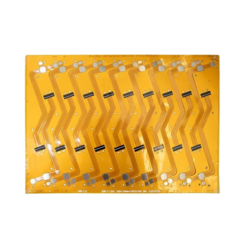
FPC Board – Flexible Circuit Board for Dynamic Flexing
A dynamic flex FPC board is designed to withstand repeated bending – thousands or even tens of thousands of cycles – without cracking conductors or losing electrical continuity.
Unlike static flex applications (where the board bends once during assembly and stays in place), dynamic flex applications require the FPC to move continuously: laptop hinges that open and close, robotic arms that articulate, printheads that scan back and forth.
For these demanding applications, standard FPC materials are insufficient. We use rolled annealed (RA) copper and optimized stackups to achieve superior flex life.
Static Flex vs. Dynamic Flex – What’s the Difference?
| Feature | Static Flex | Dynamic Flex |
|---|---|---|
| Bending frequency | Once (during assembly) | Repeated (thousands of cycles) |
| Bend radius | ≥10x thickness | ≥30x thickness |
| Copper type | ED or RA | RA copper required |
| Flex life requirement | One-time | 10,000+ cycles |
| Typical applications | Foldable phone (one-time fold) | Laptop hinge, robot arm, printhead |
| Design complexity | Lower | Higher (stress relief, no vias in bend) |
Why Dynamic Flex Requires RA Copper
| Copper Type | Grain Structure | Flex Life | Best For |
|---|---|---|---|
| ED copper (electro-deposited) | Columnar grains – cracks along grain boundaries | Poor (100-1,000 cycles) | Static flex only |
| RA copper (rolled annealed) | Horizontal grains – cracks less likely | Excellent (10,000-100,000+ cycles) | Dynamic flex (recommended) |
We use RA copper as standard for all FPC boards – no need to request it.
Key Design Considerations for Dynamic Flex FPC
| Design Element | Recommendation | Why |
|---|---|---|
| Bend radius | ≥30x flex thickness | Prevents copper fatigue |
| Bend angle | ≤180° (full fold) | Extreme angles reduce life |
| Neutral bend axis | Centered in stackup | Minimizes stress on outer layers |
| Trace routing | Perpendicular to bend axis | Minimizes stress on traces |
| Via placement | No vias in bend areas | Vias crack under repeated stress |
| Copper weight | 0.5 oz preferred | Thinner copper bends better |
| Copper type | RA copper only | ED copper cracks |
| Coverlay | Polyimide coverlay (not solder mask) | Coverlay flexes, mask cracks |
| Stiffener ends | Taper or step-cut | Prevents stress concentration |
| Flex length | Allow extra length | Prevents tension at endpoints |
Dynamic Flex Life Expectations
| Bend Radius (vs. thickness) | Expected Cycles (RA copper) | Application Example |
|---|---|---|
| 30x thickness | 10,000-20,000 cycles | Standard dynamic flex (hinges) |
| 40x thickness | 30,000-50,000 cycles | High-cycle applications |
| 50x thickness | 100,000+ cycles | Premium long-life design |
| 20x thickness | 1,000-5,000 cycles | Limited dynamic use (not recommended) |
| 10x thickness | Not for dynamic | Static flex only |
Example: 0.1mm flex thickness, 3mm bend radius = 30x – suitable for 10,000+ cycles.
Technical Specifications for Dynamic Flex FPC
| Parameter | Our Capability |
|---|---|
| Layer count | 1 to 4 layers (6 on request) |
| Board thickness | 0.1mm to 0.4mm |
| Copper weight | 0.5 oz or 1 oz |
| Copper type | RA copper standard (rolled annealed) |
| Min trace width/spacing | 3 mil / 3 mil (0.075mm) |
| Min drill size | 0.15mm mechanical, 0.10mm laser |
| Bend radius (dynamic) | ≥30x flex thickness |
| Bend radius (static) | ≥10x flex thickness |
| Expected flex life | 10,000-100,000+ cycles (depending on radius) |
| Coverlay type | Polyimide (yellow or black) |
| Coverlay thickness | 0.5 mil or 1 mil |
| Surface finish | ENIG (preferred for dynamic flex) |
| Stiffeners | FR4, polyimide, or metal (outside bend areas) |
Typical Dynamic Flex Stackup (2-Layer)
| Layer | Material | Thickness | Function |
|---|---|---|---|
| Coverlay (top) | Polyimide | 0.5 mil | Protects traces |
| Copper L1 | RA copper, 0.5 oz | 0.7 mil | Signal traces |
| Adhesive | Acrylic or epoxy | 0.5-1 mil | Bonding |
| Polyimide core | DuPont Kapton | 1-2 mil | Base insulation |
| Adhesive | Acrylic or epoxy | 0.5-1 mil | Bonding |
| Copper L2 | RA copper, 0.5 oz | 0.7 mil | Signal / ground |
| Coverlay (bottom) | Polyimide | 0.5 mil | Protects traces |
| Total thickness | ~0.15-0.2mm |
Applications for Dynamic Flex FPC
| Application | Flex Type | Bend Cycles per Day | Expected Life |
|---|---|---|---|
| Laptop hinge | 180° fold/unfold | 1-10 cycles | 5+ years (10,000+ cycles) |
| Foldable phone | 180° fold/unfold | 20-50 cycles | 3-5 years (30,000+ cycles) |
| Robotic arm | 90°-180° articulation | 100-1,000 cycles | 1-2 years (50,000+ cycles) |
| Printhead / scanner | Linear sliding | 1,000+ cycles/day | 1-2 years (100,000+ cycles) |
| Medical robot | Precise articulation | 10-100 cycles | 10+ years (critical) |
| Automotive folding mirror | 90° fold | 10-20 cycles/day | 10+ years (50,000+ cycles) |
| Industrial actuator | Continuous articulation | 1,000+ cycles/day | 1 year (300,000+ cycles) |
| Wearable (wrist strap) | Curved to flat | 10-50 cycles/day | 2-3 years (20,000+ cycles) |
Design Guidelines for Maximum Flex Life
| Guideline | Recommendation |
|---|---|
| Bend radius | As large as possible – 50x thickness ideal |
| Copper weight | 0.5 oz (1 oz max for dynamic) |
| Copper type | RA copper only |
| Trace routing | Perpendicular to bend axis |
| Trace width | Consistent – no necking in bend area |
| Via placement | No vias in bend area (≥5mm from bend start) |
| Multiple flex layers | Minimize – more layers = thicker = larger radius |
| Coverlay | Polyimide coverlay (not solder mask) |
| Stiffener edge | Taper or step-cut – no sharp transition |
| Flex length | Allow slack – no tension at endpoints |
| Shielding | Use flexible shielding (silver ink, not solid copper) |
Common Dynamic Flex Failure Modes
| Failure Mode | Cause | Prevention |
|---|---|---|
| Copper cracking | Bend radius too tight, ED copper | Use RA copper, increase radius |
| Coverlay cracking | Low-quality coverlay, tight radius | High-quality polyimide, larger radius |
| Adhesive delamination | Poor adhesion, repeated flex | High-temperature adhesive, proper cure |
| Via barrel cracks | Vias in bend area | No vias in bend area |
| Stiffener edge stress | Sharp stiffener edge | Tapered or step-cut stiffener |
Why Choose Our Dynamic Flex FPC Boards?
| Feature | What You Get |
|---|---|
| RA copper standard | Withstands 10,000+ dynamic flex cycles |
| Optimized stackup | Neutral bend axis centered |
| No vias in bend areas | DFM review catches issues |
| Polyimide coverlay | Flexes without cracking |
| Engineering support | Bend radius analysis, flex life prediction |
| Prototype available | Test your dynamic flex design |
| ISO9001 & UL certified | Quality guaranteed |
Order Process for Dynamic Flex FPC
Upload Gerber files – specify dynamic flex, bend radius, cycles required
Free DFM review – we verify RA copper, bend radius, via placement
Receive quotation – based on complexity and flex requirements
First article (recommended) – 5-20 pieces for flex life testing
Production – built with RA copper and optimized stackup
100% electrical test – including flex continuity after test bending
Secure shipping
Designing for dynamic flex? Contact us for engineering support. We help optimize bend radius, stackup, and material selection for maximum flex life.