 PCB & PCBA Manufacturer
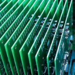
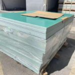
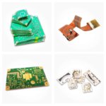
High TG FR4 PCB – TG 170°C for Lead-Free Assembly
The transition to lead-free assembly has fundamentally changed PCB manufacturing requirements. Lead-free solders (SAC305, SAC405) require higher reflow temperatures – typically 245°C to 260°C peak – compared to 220°C for leaded solder. Standard FR4 with TG (glass transition temperature) of 130°C-140°C can soften, warp, or degrade at these temperatures, leading to reliability issues.
The High TG FR4 PCB with TG 170°C is specifically engineered for lead-free assembly, maintaining mechanical stability and reliability through the higher thermal demands of modern manufacturing.
What is Glass Transition Temperature (TG)?
TG (Glass Transition Temperature) is the temperature at which the resin matrix in FR4 changes from a rigid, glass-like state to a soft, rubbery state. Above TG, the material:
Expands significantly (higher CTE – Coefficient of Thermal Expansion)
Loses mechanical strength
Becomes more susceptible to warpage
Reduces adhesion to copper
| TG Rating | Temperature | Typical Use |
|---|---|---|
| Standard TG | 130°C – 140°C | Leaded assembly, basic commercial products |
| Medium TG | 150°C – 160°C | Transitional – limited lead-free capability |
| High TG | 170°C – 180°C | Lead-free assembly, automotive, industrial |
| Very High TG | 180°C – 200°C+ | Extreme environments, aerospace |
Our High TG FR4 PCB uses TG 170°C material – the industry standard for reliable lead-free assembly.
Why High TG is Essential for Lead-Free Assembly
| Problem with Standard TG (130°C-140°C) | How High TG (170°C) Solves It |
|---|---|
| Board warpage – PCB bows under reflow heat | Maintains flatness – no warpage |
| Via barrel cracks – Z-axis expansion cracks plated through-holes | Reduced CTE – no barrel cracks |
| Pad lifting – copper separates from laminate | Stronger adhesion – pads stay attached |
| Delamination – layers separate under thermal stress | Higher thermal stability – no delamination |
| Multiple reflow cycles – degradation after 2-3 passes | Withstands 5+ reflow cycles |
| Thick boards / heavy copper – more thermal mass = more stress | Handles thermal mass without failure |
Lead-Free Reflow Temperature Profile
| Stage | Temperature | Duration |
|---|---|---|
| Preheat | 150°C – 200°C | 60-120 seconds |
| Soak | 200°C – 217°C | 60-90 seconds |
| Reflow (above liquidus) | >217°C | 60-90 seconds |
| Peak temperature | 245°C – 260°C | 5-10 seconds |
| Cooling | ramp down | controlled |
Standard TG FR4 (130°C-140°C) softens well below peak temperature (starts at ~140°C, fully soft by 170°C). High TG FR4 (170°C) softens significantly higher, maintaining mechanical stability through most of the profile.
Technical Specifications for High TG FR4 PCB
| Parameter | High TG Capability |
|---|---|
| Glass Transition Temperature (TG) | 170°C minimum (TG 170°C) |
| Decomposition Temperature (TD) | 330°C minimum (IPC-4101 spec) |
| Z-axis CTE (50-260°C) | <3.5% (prevents via cracking) |
| Peak reflow temperature | 260°C (lead-free compatible) |
| Layer count | 2 to 12+ layers |
| Board thickness | 0.6mm – 3.2mm |
| Copper weight | 1 oz – 4 oz |
| Min trace width/spacing | 4 mil / 4 mil (3 mil available) |
| Surface finish | ENIG, HASL Lead-Free, OSP, Immersion Silver |
| Inspection | 100% AOI + electrical test |
Applications Requiring High TG FR4
| Application | Why High TG is Required |
|---|---|
| Lead-free assembly (any product) | Withstands 260°C peak reflow |
| Automotive electronics | Wide temperature range (-40°C to +125°C) + lead-free |
| Industrial control (24/7) | Continuous operation, thermal cycling |
| Power supplies (high current) | Heat from power components + lead-free |
| LED lighting | Heat from LEDs + lead-free driver assembly |
| Multilayer boards (6+ layers) | Higher thermal mass requires High TG |
| Heavy copper boards (2-4 oz) | Thick copper retains heat – requires High TG |
| Thick boards (>2.0mm) | More material = more thermal expansion stress |
| Medical devices | Reliability + lead-free compliance |
| Telecom infrastructure | 24/7 operation + lead-free assembly |
Standard TG vs. High TG – Quick Comparison
| Property | Standard TG FR4 | High TG FR4 (TG 170°C) |
|---|---|---|
| Glass transition (TG) | 130°C – 140°C | 170°C minimum |
| Peak reflow capability | 240°C (marginal) | 260°C (safe) |
| Lead-free assembly | Risky – warpage, via cracks | Recommended |
| Z-axis expansion (50-260°C) | 4.0-4.5% | <3.5% |
| Multiple reflow cycles | 2-3 cycles max | 5+ cycles |
| Thermal decomposition (TD) | 300°C-310°C | 330°C+ |
| Moisture absorption | Higher | Lower |
| Cost increase vs. standard TG | Baseline | +10-20% |
| Best for | Leaded assembly, low-cost commercial | Lead-free, automotive, industrial, multilayer |
High TG Prevents Via Cracking
During lead-free reflow (260°C peak), the PCB expands in the Z-axis (thickness direction). Copper plated through-holes (vias) do not expand as much as the FR4. This differential expansion stresses the via barrel.
| Material | CTE (ppm/°C) | Expansion 50°C → 260°C |
|---|---|---|
| Copper | ~17 | ~0.36% |
| Standard TG FR4 | ~70 (above TG) | ~4.5% |
| High TG FR4 (170°C) | ~50 (above TG) | <3.5% |
The difference: High TG FR4 expands significantly less, reducing stress on via barrels and preventing cracks.
Result: Boards with High TG survive 5+ lead-free reflow cycles without via cracking. Standard TG may crack after 2-3 cycles.
High TG Prevents Board Warpage
Board warpage during reflow causes:
Poor solder paste alignment – opens/shorts on fine-pitch components
Component placement errors – pick-and-place machines struggle
Tombstoning – small passive components stand up
Standard TG: Softens above 140°C – warpage begins early in reflow profile.
High TG (170°C): Remains rigid well into the reflow profile – warpage minimized.
Why Manufacture Your High TG FR4 PCB With Us?
| Feature | What You Get for High TG Applications |
|---|---|
| TG 170°C material standard | Verified by DSC (Differential Scanning Calorimetry) testing |
| Lead-free assembly ready | Withstands 260°C peak reflow |
| Prevents warpage and via cracking | Lower Z-axis CTE |
| Multiple reflow cycles | Survives 5+ cycles for rework |
| Automotive & industrial grade | Wide temperature range support |
| 100% electrical test | Each board verified |
| Material certificates available | TG verification upon request |
Order Process for High TG FR4 PCB
Upload your Gerber files – specify High TG requirement
TG 170°C material – confirmed and sourced
Fabrication – standard FR4 process (same lead time)
Optional TG testing – DSC verification available
100% electrical test
Secure shipping with material certificates