Rigid PCB vs Flexible PCB – Rigid Flex Combo Solution
When designing an electronic product, engineers face a fundamental choice: rigid PCB, flexible PCB, or a combination of both? Each option has distinct advantages and trade-offs.
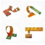
The Rigid Flex Combo Solution merges the strength and component support of rigid boards with the bendability and space savings of flexible circuits – eliminating connectors, reducing assembly time, and improving reliability.
This guide compares rigid, flexible, and rigid flex designs to help you choose the right solution for your application.
Rigid PCB vs. Flexible PCB vs. Rigid Flex – Quick Comparison
| Feature | Rigid PCB | Flexible PCB (FPC) | Rigid Flex (Combo) |
|---|---|---|---|
| Construction | Solid FR4 material | Thin polyimide film | Rigid FR4 + flexible polyimide |
| Bendability | None – breaks if bent | Yes – designed to flex | Rigid sections fixed, flex sections bend |
| Component support | Excellent – heavy components | Limited – light components only | Excellent on rigid sections |
| Space efficiency | Good | Excellent – folds into tight spaces | Very good |
| Weight | Heavier | Very light | Moderate |
| Connectors needed | Yes – for board-to-board | Fewer – can integrate | None – single integrated board |
| Reliability | Good (connectors are weak points) | Good | Excellent – no connectors |
| Assembly complexity | Moderate (multiple boards + cables) | Simple (one board) | Simple (one board) |
| Cost (low volume) | Low | Moderate | Higher |
| Cost (high volume) | Low | Low | Moderate (often lower than rigid + cable + flex) |
| Best for | Standard electronics | Simple flexing applications | Complex folding, high reliability |
The Problem with Rigid PCB + Flexible PCB + Connectors
Many designs use separate rigid PCBs connected by flexible cables or wire harnesses with connectors at each end.
| Issue | Consequence |
|---|---|
| Multiple connectors | Potential failure points (vibration, corrosion, mating cycles) |
| Cable management | Assembly time, routing complexity |
| Signal integrity | Connectors and cables degrade high-speed signals |
| Space inefficiency | Connectors take space, cables need routing room |
| Higher BOM cost | Connectors, cables, separate boards |
| Assembly labor | Multiple parts to assemble |
Rigid flex eliminates all of these issues – one integrated board, no connectors, no cables.
The Rigid Flex Advantage
| Advantage | How It Helps Your Design |
|---|---|
| No connectors | Eliminates connector costs, reduces failure points |
| No cables | Saves assembly time, improves signal integrity |
| Folds into 3D shapes | Fits into tight, irregular enclosures |
| Lighter weight | No connectors, no cable harnesses |
| Higher reliability | Fewer interconnects = fewer failure modes |
| Lower assembly cost | One board to place, not multiple boards + cables |
| Better signal integrity | Continuous traces from rigid to flex section |
When to Choose Each Solution
| Application Characteristic | Recommended Solution | Why |
|---|---|---|
| Standard box, no bending, low cost | Rigid PCB only | Cheapest, proven |
| Simple folding, light components | Flexible PCB only | Lightweight, low profile |
| Complex folding, heavy components | Rigid Flex | Best of both |
| High vibration environment | Rigid Flex | No connectors to fail |
| Tight enclosure with multiple folds | Rigid Flex | Fits 3D spaces |
| High reliability (medical, aerospace) | Rigid Flex | Eliminates connector failures |
| Wearables (watch, fitness band) | Flexible or Rigid Flex | Thin, bendable |
| Camera module (lens on flex, processor on rigid) | Rigid Flex | Ideal – rigid for components, flex for positioning |
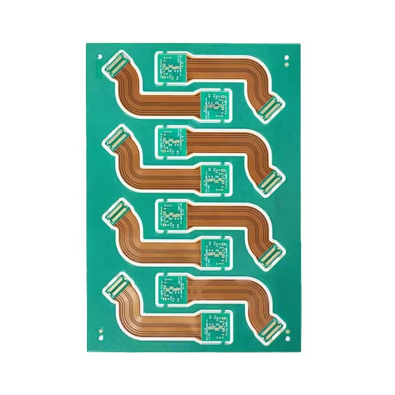
Rigid Flex Typical Stackup
A standard rigid flex construction consists of:
| Layer | Material | Thickness (typical) |
|---|---|---|
| Coverlay (top) | Polyimide film | 0.5 mil |
| Flexible copper layer | Rolled annealed copper | 0.5-1 oz |
| Polyimide core | Flexible base material | 1-2 mil |
| Flexible copper layer (bottom) | Rolled annealed copper | 0.5-1 oz |
| Coverlay (bottom) | Polyimide film | 0.5 mil |
| FR4 rigid sections (additional layers on rigid areas only) | FR4 + prepreg + copper | Varies |
Key feature: Rigid sections have additional FR4 layers bonded to the flex core. The flex section remains unbonded and free to bend.
Rigid Flex Design Considerations
| Consideration | Recommendation |
|---|---|
| Bend radius | Minimum 10x flex thickness (e.g., 1mm radius for 0.1mm flex) |
| Dynamic vs. static flex | Dynamic (repeated) needs larger radius, rolled annealed copper |
| Flex layer count | 1-4 layers typical (more adds cost) |
| Via placement | Avoid vias in bend areas – they crack |
| Copper weight in flex | 0.5 oz or 1 oz – heavier copper cracks when bent |
| Coverlay vs. solder mask | Coverlay on flex sections (flexible), solder mask on rigid sections |
| Stiffeners | Add FR4 or polyimide stiffeners under components on flex tails |
Applications Best Suited for Rigid Flex Combo
| Application | Why Rigid Flex is Ideal |
|---|---|
| Wearables (smartwatch, fitness band) | Fits curved wrist, holds heavy components (battery, display) |
| Medical devices (hearing aids, endoscopes) | Tiny spaces, high reliability, no connector failure |
| Aerospace / defense | Vibration resistance, weight reduction |
| Industrial robotics | Dynamic flexing, rugged environment |
| Camera modules | Rigid for image sensor, flex for lens positioning |
| Laptop / tablet | Hinge area – connects motherboard to display |
| Automotive (sensors, infotainment) | Vibration resistance, tight spaces |
| Military radios | Folds into handheld enclosure |
Cost Comparison – Rigid + Cable + Flex vs. Rigid Flex
| Cost Factor | Rigid + Cable + Flex | Rigid Flex Combo |
|---|---|---|
| PCB fabrication (2 rigid boards + 1 flex + cable) | Higher | Lower – one integrated board |
| Connectors (2-4 connectors) | Yes – significant cost | None |
| Cable assembly | Yes – labor cost | None |
| Assembly labor | Higher (multiple parts) | Lower (one board) |
| Inventory / logistics | More SKUs to manage | One SKU |
| Total system cost | Higher | Lower or similar |
Important: Rigid flex may have higher per-board cost than a simple rigid board, but total system cost (including connectors, cables, assembly, inventory) is often lower with rigid flex.
Why Choose Our Rigid Flex Combo Solution?
| Feature | What You Get |
|---|---|
| True rigid flex integration | Continuous traces from rigid to flex sections |
| No connectors needed | Eliminate connector failure points |
| High reliability | ISO9001 & UL certified processes |
| Engineering support | Bend radius, stackup, material selection guidance |
| Prototype available | Fast turnaround for design validation |
| Volume production | Scalable to your needs |
Order Process for Rigid Flex
Upload Gerber files – specify rigid and flex layers, bend areas
Free DFM review – we verify bend radius, via placement, stackup
Receive quotation – based on your design complexity
Approve and pay – production begins
100% electrical test
Secure shipping
Still deciding between rigid, flexible, or rigid flex? Send us your requirements. We recommend the most cost-effective solution for your application.